Our commitment to excellence is evident through rigorous quality checks and audits from material procurement to packaging. We adapt to market dynamics, ensuring consistent delivery of high-quality products within set timelines for customer satisfaction.
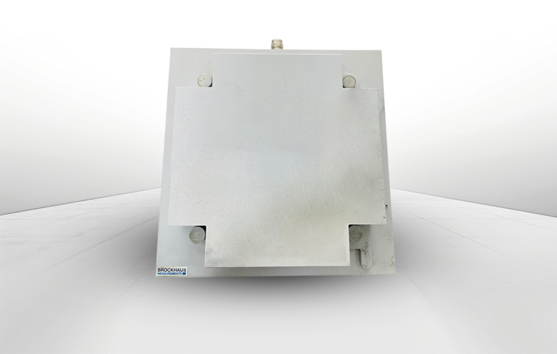
“Our infrastructure boast with a well equipped testing Laboratory, featuring state of art “Brockhaus Testing Machines”
Inhouse testing facility


